 Home automation/security has always been a passion of mine. Sure, there are plenty of commercial kits out there to buy, but I’d rather DIY, especially if it means saving a buck or two. This 2 part series will explain how to cheaply control electrical outlets in your home using an Arduino. Even if you don’t care for home automation, the information from this tutorial will give you serial access to the Arduino over the network, so you can feasibly do ANYTHING, as long as the Arduino is capable of controlling it.
So, first thing’s first, here’s what I used for my installation. Again, parts of the list may or may not be necessary based on what you are trying to accomplish:
- Arduino Uno – This serves as the brain for the project. Any microcontroller capable of serial control will do though.
- RF Outlets – I bought a 3 pack of RF controlled outlets at Target during the holidays. See the pic below. The outlets come with a single remote, and each is assigned an on/off button pair. Our goal is to have the Arduino emulate button presses on the remote to switch on/off the different outlets.
- Home Server – This was probably the most time consuming portion, but it’s actually not terrible to set up your own server. When we’re all done, you’ll be able to point a web browser to your home based server and view a webpage that will enable you to turn on/off the outlets. The home server requires a VERY low-end computer, and home network/internet access. Mine is built on an old HP Vectra, running Windows XP, and Apache Server with PHP installed.
- Opto-isolators – Since we need to emulate a button press, it’s not just as easy as allowing the Arduino to pull one of its pins high/low. We actually need to close a circuit. This is what the very cheap photocouplers will do. I got mine from FUTURLEC for $0.60 each. Part Number was TLP521-4 Quad PhotoCoupler.
So, in part 1 of the tutorial, we’re going to figure out the Arduino to Outlet portion. If you don’t care about this and just want to see how to control an Arduino from the web, skip on to part 2.
Arduino To Outlet Control:
So, our goal for this portion is to have the Arduino control our RF outlets. The easiest way to do this is by having it directly interface with the remote that comes with the outlet. So, here are the steps to make that work:
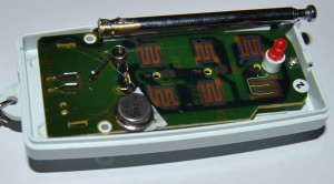
Take apart the RF outlet remote control. You can see my disassembled remote below. I found that the buttons closed a circuit between an electrical trace on the board and the 3V from the coin cell battery that powers the remote. It was easy to check this, I just held a wire against the battery and pressed the other end onto the specific traces, and the outlets flipped on/off.
Click the image to enlarge. If you apply 3V to the traces outline in BLUE, Outlet #1 gets the “ON” signal. If you apply 3V to the green trace, Outlet #1 gets the “OFF” signal. The other traces are for the other outlets.
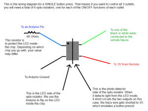
So the next step is getting the Arduino to take care of bringing the traces HIGH to 3V. The problem is that the Arduino digital pins operate at a HIGH 5V. There are several ways to go about this, but I chose to use a little device called an Opto-isolator. They are pretty nifty. Click here to learn more, but the chip basically houses one or more LED/photodetector pairs. When you bring the LED high (with the Arduino, in this case), the photodetector sees the light and “nearly” closes the two pins on the other side. I say “nearly”, because they go from open circuit to ~100 ohms, which was enough to simulate the button press for me.
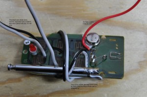
Luckily, the remote board had holes drilled in the traces I needed to access, so I was able to stick a wire in the hole, solder it to the pad on the back of the remote, and then all I had to do was have the trace wire on one pin of the opto-isolator output, and the 3V pin on the other. Click on the image below for wire descriptions.
Here’s a wiring diagram, since the image above is probably more confusing than helpful.
 Since there are actually 6 of those in our design, it’s prudent to make a common trace for the 3V and the Arduino ground, otherwise you’ll have lots of wires and probably run out of pins.
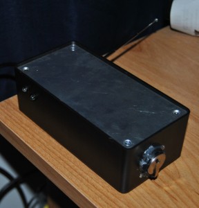
That about sums it up for the hardware. I added a few extras to mine, including LEDs on the outside case so I could visibly see the status of each remote. Additionally, I relocated the battery holder from inside my box (with the remote) to the outside, so I could change it without opening the box. I also drilled a hole in my box for the USB cable and the remote antenna. Check it out:
Now for the Arduino code. Later, when we get to our Server side of the tutorial, we will see that the Arduino needs a serial command for each of the actions we want to perform. In this case, we need to pull HIGH the blue pin from the diagram above for whatever specific outlet and action we want. Here’s my code, and the explanation follows.
int remoteOneON = 53; //pin for 1 ON int remoteOneOFF = 51; //pin for 1 OFF int remoteTwoON = 52; //pin for 2 ON int remoteTwoOFF = 50; //pin for 2 OFF int remoteOneInd = 22; //pin for 1 LED int remoteTwoInd = 23; //pin for 2 LED int incomingByte = 0; //variable to hold incoming Serial data // The setup() method runs once, when the sketch startsvoid setup() { // initialize the digital pins as outputs: pinMode(remoteOneON, OUTPUT); pinMode(remoteOneOFF, OUTPUT); pinMode(remoteTwoON, OUTPUT); pinMode(remoteTwoOFF, OUTPUT); pinMode(remoteOneInd, OUTPUT); pinMode(remoteTwoInd, OUTPUT); digitalWrite(remoteOneInd, HIGH); //turn on #1 indicator LED digitalWrite(remoteTwoInd, HIGH); //turn on #2 indicator LED digitalWrite(remoteOneOFF, HIGH); //send the command to turn OFF #1 delay(1500); //wait 1.5s digitalWrite(remoteOneOFF, LOW); //pull the pin Low digitalWrite(remoteTwoOFF, HIGH); // send the command to turn OFF #2 delay(1500); //wait 1.5s digitalWrite(remoteTwoOFF, LOW); //pull the pin Low digitalWrite(remoteOneInd, LOW); //turn off #1 LED digitalWrite(remoteTwoInd, LOW); //turn off #2 LED Serial.begin(9600); //initialize serial comm at 9600 baud } // the loop() method runs over and over again, // as long as the Arduino has power void loop() { if (Serial.available() > 0) { //if Serial data is available incomingByte = Serial.read(); //store the data in incoming byte if(incomingByte == 'A'){ //A digitalWrite(remoteOneInd, HIGH); digitalWrite(remoteOneON, HIGH); delay(1500); digitalWrite(remoteOneON, LOW); } else if(incomingByte == 'B'){ //B digitalWrite(remoteOneInd, LOW); digitalWrite(remoteOneOFF, HIGH); delay(1500); digitalWrite(remoteOneOFF, LOW); } else if(incomingByte == 'C'){ //C digitalWrite(remoteTwoInd, HIGH); digitalWrite(remoteTwoON, HIGH); delay(1500); digitalWrite(remoteTwoON, LOW); }else if(incomingByte == 'D'){ //D digitalWrite(remoteTwoInd, LOW); digitalWrite(remoteTwoOFF, HIGH); delay(1500); digitalWrite(remoteTwoOFF, LOW); } } }
So, here’s what happens. After initializing all our variables and turning OFF all the outlets on a reset (during Setup), we go into our main loop. During the main loop, the Arduino waits for incoming serial data. If it receives something, it will evaluate that data and perform a specific action. For example, if we send the Arduino an ‘A’, it will first turn on the #1 indicator LED, then it will pull HIGH the #1 ON pin, which turns on the LED in the opto-isolator, which shorts the button trace in our hacked remote to 3V, and we get a button press! We wait 1.5s while the command goes out, and then pull everything (except the indicator LED) back to LOW. The rest of the code follows the same logic. Wait for serial command –> perform action based on received command –> pull everything back low –> Wait for next command.
Next, we have the second part of the tutorial, which concerns itself with sending the Arduino serial commands from the web .


Pingback: Arduino Home Automation, Part 2 | Schmidt Creative Design Studio
Pingback: » Arduino Home Automation, Part 2
kirgy
MD Schmidt
Robert
MD Schmidt
Pingback: Arduino Home Automation, Part 2 | CastleSeven